ポリゴンメッシュをワイヤーフレームだけにする (スクリプト)
ポリゴンメッシュのワイヤーフレームだけをジオメトリとして残すためのスクリプトです。
エッジベベルを使用してエッジ部分だけを残す手順では、非平面が含まれるとうまく処理できない場合が多いです。
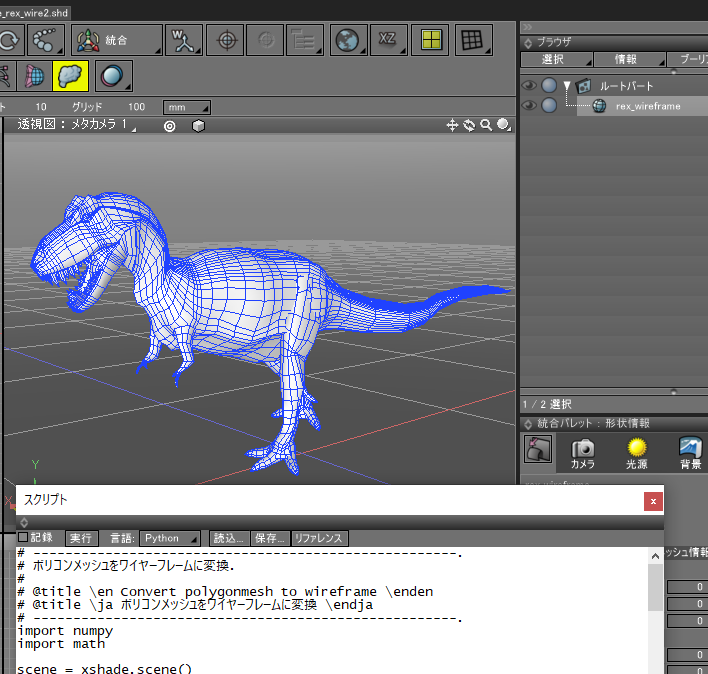
ブラウザでポリゴンメッシュを選択し、以下のスクリプトを実行すると、
指定の幅のワイヤーフレームをジオメトリとして生成します。
import numpy
import math

scene = xshade.scene()

# -----------------------------------------------.
# 指定のポリゴンメッシュで、面に属さない頂点を削除.
# -----------------------------------------------.
def cleanupMeshVertices (shape):
    # 面で参照される頂点を取得.
    versCou  = shape.total_number_of_control_points
    facesCou = shape.number_of_faces
    vUsedList = [0] * versCou
    for fLoop in range(facesCou):
        f = shape.face(fLoop)
        vCou = f.number_of_vertices
        for i in range(vCou):
            vUsedList[ f.vertex_indices[i] ] = 1

    # 参照されない頂点を削除.
    shape.begin_removing_control_points()

    for i in range(versCou):
        if vUsedList[i] == 0:
            shape.remove_control_point(i)

    shape.end_removing_control_points()

# -----------------------------------------------.
# 2つの直線の交点を計算。 (x, y, z)の要素のZは0.0とする.
# pA1 - pA2 と pB1 - pB2 の直線交点を計算する.
# -----------------------------------------------.
def calcLinesCrossPos (pA1, pA2, pB1, pB2):
    dV = (pA2[1]-pA1[1]) * (pB2[0]-pB1[0]) - (pA2[0]-pA1[0]) * (pB2[1]-pB1[1])
    if math.fabs(dV) < 1e-5:
        return pA2

    d1 = pB1[1] * pB2[0] - pB1[0] * pB2[1]
    d2 = pA1[1] * pA2[0] - pA1[0] * pA2[1]

    fx = d1 * (pA2[0] - pA1[0]) - d2 * (pB2[0] - pB1[0])
    fx /= dV
    fy = d1 * (pA2[1] - pA1[1]) - d2 * (pB2[1] - pB1[1])
    fy /= dV

    # ラフにクリッピング.
    fMinX = min(min(min(pA1[0], pA2[0]), pB1[0]), pB2[0])
    fMaxX = max(max(max(pA1[0], pA2[0]), pB1[0]), pB2[0])
    fMinY = min(min(min(pA1[1], pA2[1]), pB1[1]), pB2[1])
    fMaxY = max(max(max(pA1[1], pA2[1]), pB1[1]), pB2[1])
    dx = (fMaxX - fMinX) * 0.5
    dy = (fMaxY - fMinY) * 0.5
    fMinX -= dx
    fMaxX += dx
    fMinY -= dy
    fMaxY += dy
    if fx < fMinX or fx > fMaxX or fy < fMinY or fy > fMaxY:
        return pA2

    return numpy.array([fx, fy, 0.0])

# -----------------------------------------------.
# 頂点座標の配列から、バウンディングボックスサイズを計算.
# -----------------------------------------------.
def calcBondingBoxSize (versList):
    if len(versList) == 0:
        return [0.0, 0.0]
    minX = maxX = versList[0][0]
    minY = maxY = versList[0][1]

    for p in versList:
        minX = min(minX, p[0])
        maxX = max(maxX, p[0])
        minY = min(minY, p[1])
        maxY = max(maxY, p[1])

    return [maxX - minX, maxY - minY]

# -----------------------------------------------.
# ポリゴンメッシュをワイヤーフレームに変換.
# -----------------------------------------------.
def convMeshToWireframe (shape, lineWidth):
    if shape.type != 7:   # ポリゴンメッシュでない場合.
        return None

    shape.setup_plane_equation()

    zUpNormal = numpy.array([0.0, 0.0, 1.0])
    fMinDist = 1e-5

    faceOrgIndicesList = []
    newVersList = []
    facesCou = shape.number_of_faces
    versCou  = shape.total_number_of_control_points
    for fLoop in range(facesCou):
        faceD = shape.face(fLoop)
        fvCou = faceD.number_of_vertices
        if fvCou <= 2:
            continue

        # (x,y,z)が面法線相当.
        fNormal = shape.get_plane_equation(fLoop)

        # 頂点座標を一時格納.
        vIndices = faceD.vertex_indices
        versIndices = []
        vers = []
        fCenterPos = numpy.array([0.0, 0.0, 0.0])
        for i in range(fvCou):
            p = shape.vertex(vIndices[i]).position
            p = numpy.array([p[0], p[1], p[2]])
            fCenterPos += p
            vers.append(p)
            versIndices.append(vIndices[i])
        fCenterPos /= float(fvCou)

        # 法線座標系への変換行列。Z軸方向を法線とする.
        xV = numpy.array([0.0, 0.0, 0.0])
        minLenV = -1.0
        for i in range(fvCou):
            xV = vers[(i + 1) % fvCou] - vers[i]
            lenV = numpy.linalg.norm(xV)
            if minLenV < 0.0 and lenV > fMinDist:
                xV /= lenV
                minLenV = lenV
                break
        if minLenV < 0.0:
            continue

        normalV = numpy.array([fNormal[0], fNormal[1], fNormal[2]])
        fnMatrix = numpy.matrix(numpy.identity(4))
        yV = numpy.array([0.0, 0.0, 0.0])
        zV = normalV
        xV  = numpy.cross(normalV, xV)
        yV  = numpy.cross(normalV, xV)

        lenV = numpy.linalg.norm(xV)
        if lenV == 0.0:
            continue
        xV /= lenV
        lenV = numpy.linalg.norm(yV)
        if lenV == 0.0:
            continue
        yV /= lenV

        fnMatrix[0, 0] = xV[0]
        fnMatrix[0, 1] = xV[1]
        fnMatrix[0, 2] = xV[2]
        fnMatrix[1, 0] = yV[0]
        fnMatrix[1, 1] = yV[1]
        fnMatrix[1, 2] = yV[2]
        fnMatrix[2, 0] = zV[0]
        fnMatrix[2, 1] = zV[1]
        fnMatrix[2, 2] = zV[2]

        fnMatrixInv = fnMatrix.I

        # 頂点間の距離がfMinDistよりも小さい場合は重複とみなして頂点を削除.
        removeI = []
        for i in range(fvCou):
            p0 = vers[i]
            p1 = vers[(i + 1) % fvCou]
            lenV = numpy.linalg.norm(p1 - p0)
            if lenV < fMinDist:
                if i + 1 < fvCou:
                    removeI.append(i)

        if len(removeI) > 0:
            for i in reversed(removeI):
                vers.pop(i)
                versIndices.pop(i)

        fvCou = len(vers)
        if fvCou <= 2:
            continue

        # 頂点座標をZ軸向きの座標系に変換.
        # この変換で、(平面上の面の場合は)Z値は0.0になる.
        for i in range(fvCou):
            p = vers[i]
            p2 = p - fCenterPos
            p2 = numpy.array([p2[0], p2[1], p2[2], 1.0])
            retM = numpy.dot(p2, fnMatrixInv)  # 法線座標系に変換.
            p2 = [retM[0,0], retM[0,1], retM[0,2]]
            vers[i] = numpy.array([p2[0], p2[1], p2[2]])

        # 面の法線座標での中心 ([0, 0, 0]になる).
        fCenter = numpy.array([0.0, 0.0, 0.0])
        for i in range(fvCou):
            fCenter += vers[i]
        fCenter /= float(fvCou)

        # バウンディングボックスサイズを計算.
        fBBoxSize = calcBondingBoxSize(vers)
        bbMinLen = min(fBBoxSize[0], fBBoxSize[1])

        # lineWidthの値を調整.
        lineWidth2 = min(lineWidth, bbMinLen * 0.3)

        # エッジを内側にlineWidth2分シフト.
        tmpVers = []
        for i in range(fvCou):
            e0 = i
            e1 = (i + 1) % fvCou
            p0 = vers[e0] - fCenter
            p1 = vers[e1] - fCenter
            p0_2 = numpy.array([p0[0], p0[1], 0.0])
            p1_2 = numpy.array([p1[0], p1[1], 0.0])
            dirV = p1_2 - p0_2
            lenV = numpy.linalg.norm(dirV)
            if lenV < 1e-5:
                continue
            dirV /= lenV
            dirV2 = numpy.cross(dirV, -zUpNormal)
            lenV = numpy.linalg.norm(dirV2)
            if lenV < 1e-5:
                continue
            dirV2 /= lenV
            dirV3 = dirV2 * lineWidth2
            p0_3 = p0_2 + dirV3
            p1_3 = p1_2 + dirV3

            tmpVers.append(p0_3 + fCenter)
            tmpVers.append(p1_3 + fCenter)

        # エッジの交点を計算.
        crossVers = []
        iPos = 0
        for i in range(fvCou):
            p0 = tmpVers[iPos]
            p1 = tmpVers[iPos + 1]
            if i == 0:
                iPos2 = (fvCou - 1) * 2
                p0_prev = tmpVers[iPos2]
                p1_prev = tmpVers[iPos2 + 1]
            else:
                p0_prev = tmpVers[iPos - 2]
                p1_prev = tmpVers[iPos - 1]

            # p0_prevを通りvDir_prevの直線と、p0を通りvDirの直線との交点を計算.
            p = calcLinesCrossPos(p0, p1, p0_prev, p1_prev)
            crossVers.append(p)
            iPos += 2

        # crossVersを元のローカル座標に戻す.
        for i in range(fvCou):
            p = crossVers[i]
            p = numpy.array([p[0], p[1], p[2], 1.0])
            retM = numpy.dot(p, fnMatrix)
            p2 = numpy.array([retM[0,0], retM[0,1], retM[0,2]]) + fCenterPos
            crossVers[i] = p2

        newVersList.append(crossVers)
        faceOrgIndicesList.append(versIndices)

    if len(newVersList) >= 1:
        nameStr = shape.name + '_wireframe'
        scene.begin_creating()
        pMesh = scene.begin_polygon_mesh(nameStr)

        # オリジナルの頂点を格納.
        for i in range(versCou):
            p = shape.vertex(i).position
            scene.append_polygon_mesh_vertex(p)
        vOffset = versCou

        # 新しいメッシュに頂点/面情報を格納.
        fIPos = 0
        fIndex = [0, 0, 0, 0]
        facesCou = len(faceOrgIndicesList)
        for fLoop in range(facesCou):
            versOrgIndices = faceOrgIndicesList[fLoop]

            newVers = newVersList[fLoop]
            for p in newVers:
                scene.append_polygon_mesh_vertex([p[0], p[1], p[2]])

            fvCou = len(newVers)
            for i in range(fvCou):
                e0 = i
                e1 = (i + 1) % fvCou
                fIndex[0] = versOrgIndices[e0]
                fIndex[1] = versOrgIndices[e1]
                fIndex[2] = fIPos + e1 + vOffset
                fIndex[3] = fIPos + e0 + vOffset
                scene.append_polygon_mesh_face(fIndex)
            fIPos += fvCou

        scene.end_polygon_mesh()
        pMesh.make_edges()   # 稜線を生成.
        pMesh.cleanup_redundant_vertices()  # 重複頂点を削除.

        # 面に属さない頂点を削除.
        cleanupMeshVertices(pMesh)

        scene.end_creating()

        # 元の形状を隠す.
        shape.render_flag = 0
        shape.hide()

        return pMesh

    return None

shape = scene.active_shape()

# -------------------------------------.
# ダイアログボックスの作成.
# -------------------------------------.
dlg = xshade.create_dialog_with_uuid('5C3E7C03-B4D6-40CC-B574-24F9C31206C0')

width_id = dlg.append_float('幅', 'mm')

# デフォルトボタンを追加.
dlg.append_default_button()

# 値を指定.
dlg.set_value(width_id, 10.0)

# デフォルト値を指定.
dlg.set_default_value(width_id, 10.0)

# ダイアログボックスを表示.
if dlg.ask("ポリゴンメッシュをワイヤーフレームに変換"):
    # ダイアログボックスでの値を取得.
    lineWidth = dlg.get_value(width_id)

    # 選択形状を取得.
    shapesList = []
    for shape in scene.active_shapes:
        shapesList.append(shape)

    # ポリゴンメッシュをワイヤーフレームに変換.
    newShapesList = []
    for shape in shapesList:
        nShape = convMeshToWireframe(shape, lineWidth)
        if nShape != None:
            newShapesList.append(nShape)

    if len(newShapesList) == 0:
        print 'ポリゴンメッシュを選択してください。'
    else:
        scene.active_shapes = newShapesList
使い方
スクリプトウィンドウに、上記のコードをコピー&ペーストします。
ブラウザでポリゴンメッシュを選択します。複数選択しても動作します。

スクリプトの実行ボタンを押します。
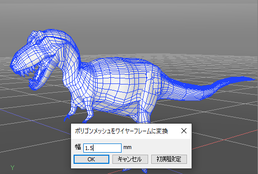
「ポリゴンメッシュをワイヤーフレームに変換」ダイアログボックスの「幅」にワイヤーフレームの幅を入力し、OKボタンを押します。
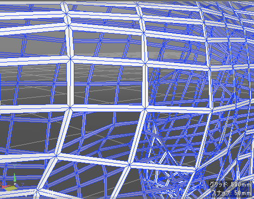
なお、面が隣接している部分は「幅 x 2」に面が貼られます。

ポリゴン数が多いほど時間がかかります。
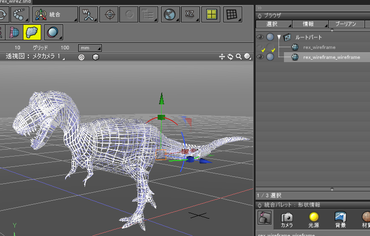
しばらく待つと、指定の幅が最大になるようにワイヤーフレームのみのポリゴンメッシュが生成されます。
この幅より小さい面の場合は、面ごとに自動的に幅のサイズが調整されます。
元の形状は、ブラウザ上で非表示になります。

透視図でズームしていくと以下のように、元の面の内側に指定の幅の面が貼られます。

そのため、最大で「面数 x 面ごとの稜線数」の面が生成されることになります。